

Every millimeter counts in Surface Mount Technology assembly. As component packages shrink from 0402 to 0201 to 008004, the tolerance for placement error narrows to fractions of a millimeter. Miss by too much, and solder joints fail. Align poorly on fine-pitch parts, and bridging destroys expensive assemblies.
Two unsung heroes maintain placement accuracy across millions of pick-and-place cycles: fiducial marks and tooling holes. These seemingly simple design features tell your placement equipment exactly where to go—and make the difference between reliable assemblies and costly rework.
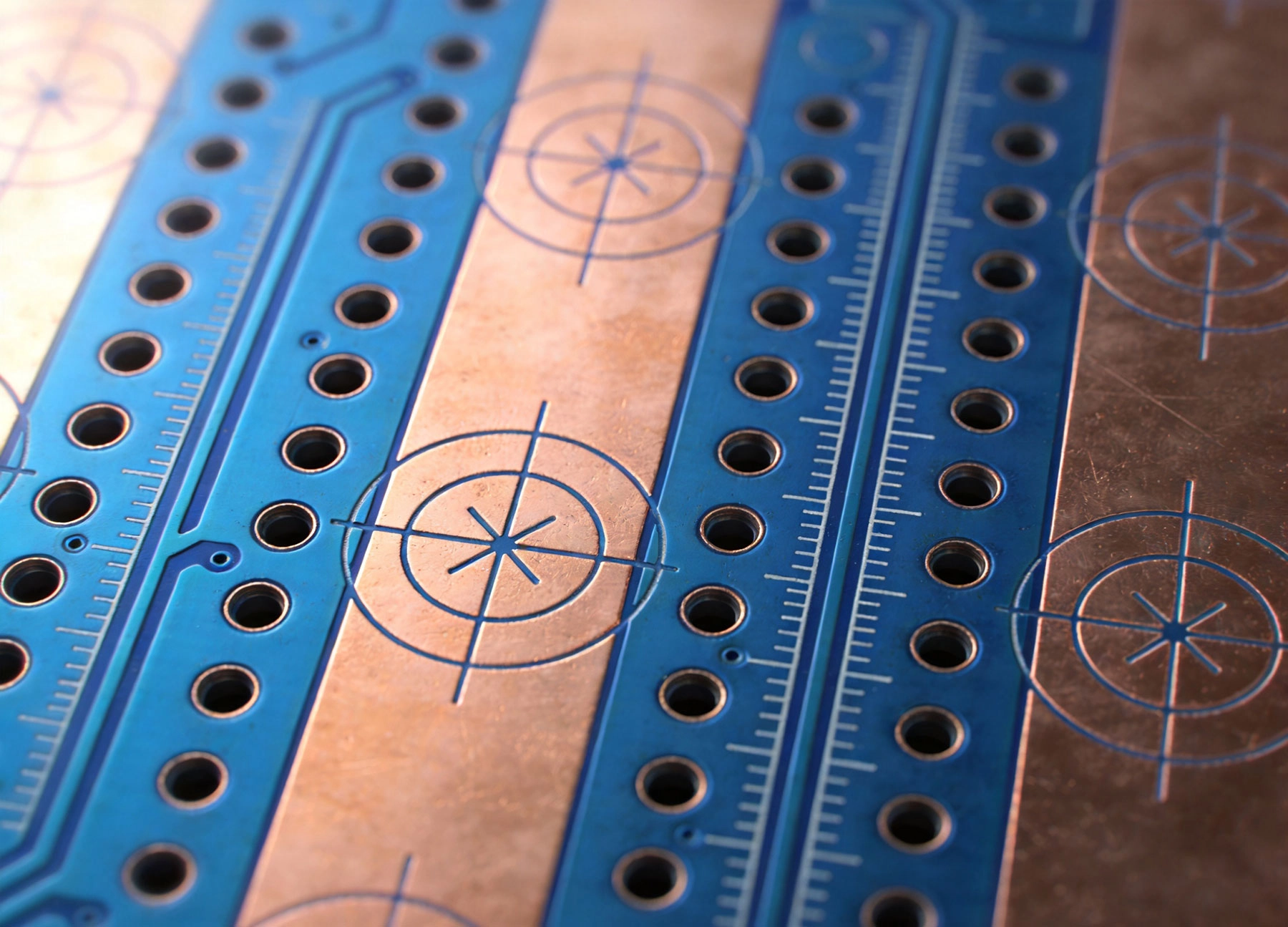
Fiducial marks are precisely placed reference features on your Pcb that placement machines use to calibrate their vision systems. The machine camera identifies these marks, calculates their position relative to the board edges, and uses this information to correct for any offset, rotation, or scaling variations in the board.
Think of fiducials as the GPS coordinates of your Pcb. Without them, the placement machine operates blind—trusting that the board sits exactly where the program expects. With them, the machine sees exactly where the board actually is.
A standard fiducial consists of a filled circle of copper on the board surface, typically 1.0mm to 3.0mm in diameter, surrounded by a clear area (solder mask opening) with no other copper features nearby. The contrast between the copper circle and the surrounding mask creates a clear target for machine vision.
Crosshairs, concentric circles, and other geometries exist, but the filled circle remains the industry standard because it provides consistent edges from any viewing angle and works reliably with standard vision processing algorithms.
Several trends make fiducial marks increasingly critical:
The transition from through-hole to surface mount was just the beginning. Today's 01005 and 008004 resistors push placement accuracy to extremes. A 01005 component measures roughly 0.4mm × 0.2mm—smaller than a grain of sand. At these scales, even microscopic placement errors cause joint failures.
Manufacturing efficiency drives boards larger. Bigger panels mean more Thermal Stress during processing and greater potential for dimensional changes. A panel that stretches or warps slightly during reflow may shift component positions enough to cause failures without fiducial correction.
Fine-pitch ICs with 0.3mm or 0.4mm lead spacing demand precise alignment. Bga packages with balls hidden beneath the package require absolute positional accuracy. Without fiducials, accumulated Manufacturing variations make these parts nearly impossible to place reliably.
Modern assemblies mix surface mount with through-hole components, press-fit connectors, and manual assembly steps. Each process step potentially shifts the board slightly. Fiducials at different board locations let equipment compensate for these variations throughout production.
Different fiducial types serve different purposes in pcb assembly.
Global fiducials—also called panel fiducials or reference fiducials—appear once per panel or once per individual board within a panel. Most SMT placement systems require at least two global fiducials to calculate board position, rotation, and scaling. Three fiducials provide redundancy and enable compensation for non-linear distortions.
Standard practice places global fiducials in board corners or at opposite ends of the assembly, maximizing the measurement baseline for accurate position calculation.
Local fiducials—sometimes called component fiducials or fine-pitch fiducials—appear near fine-pitch component areas. They provide local reference points that correct for distortions specific to that board region.
High-density assemblies with multiple fine-pitch BGAs or CSPs often benefit from local fiducials near each sensitive component. This approach limits the distance over which the machine must interpolate positions, reducing accumulated error.
Pattern fiducials use specific geometric patterns designed for particular vision systems. Some manufacturers specify crosshair patterns or bullseye designs that their equipment processes more reliably. Check your placement machine's documentation for recommended patterns.
Proper fiducial design ensures reliable machine recognition and accurate placement.
Fiducial diameter typically ranges from 1.0mm to 3.0mm. Larger marks are easier for machines to find but consume board space. Smaller marks allow denser fiducial placement but require higher camera resolution and may suffer recognition failures more often.
For standard production boards, 1.5mm to 2.0mm diameter works well across most equipment types. Fine-pitch assemblies may benefit from 2.0mm to 3.0mm marks for maximum reliability.
The area surrounding a fiducial must be clear of other copper features. A minimum clear zone of 1.5mm to 2.0mm around the fiducial edge prevents stray copper from confusing the vision system. Routing traces too close to a fiducial creates recognition failures.
For high-precision applications, increase the clear zone to 3.0mm or more. The extra space improves contrast and reduces edge effects that can shift recognition calculations.
Position global fiducials where they remain visible throughout the assembly process. Avoid placing them near panel breakaway tabs, assembly rails, or areas covered by fixtures. Fiducials obscured by components or fixtures become useless.
Consider board flex during handling. Fiducials near board edges may experience different mechanical conditions than those near the center. Balanced placement helps average out these variations.
Fiducial recognition depends on consistent visual contrast. Different surface finishes—HASL, ENIG, OSP—reflect light differently. Ensure your surface finish provides adequate contrast between the copper fiducial and surrounding solder mask. Some finishes require fiducials with different clear area treatments for optimal recognition.
Tooling holes are precisely positioned holes in your PCB panel that engage with pins, slots, or locators on the assembly equipment. While fiducials serve the vision system, tooling features serve the mechanical positioning system.
Tooling holes define the physical reference frame for the entire assembly process. All downstream equipment—paste printers, placement machines, reflow ovens—use tooling holes to position the board consistently.
Two main tooling hole types dominate pcb assembly:
Edge locator holes engage with pins along the panel edge. The panel slides onto precisely positioned pins that locate the board horizontally and vertically. This approach is simple and reliable but requires dedicated tooling for each panel size.
Slot tooling uses elongated holes that engage with wider rails or brackets. Slots provide more adjustment range than round holes and accommodate panel size variations better. Many modern equipment designs prefer slot tooling for its flexibility.
Tooling holes and fiducials serve complementary but distinct functions. Tooling holes provide rough mechanical positioning—the board sits in the right general location. Fiducials provide precise optical correction—the vision system adjusts for any remaining offset.
You cannot substitute one for the other. A board with tooling holes but no fiducials suffers from cumulative positioning errors. A board with fiducials but no tooling holes may shift during handling or fail to engage properly with equipment fixtures.
Industry standards define recommended tooling hole positions. IPC guidelines specify tooling features at panel corners, typically 3.0mm to 5.0mm from panel edges. These positions accommodate standard equipment designs and maximize the measurement baseline.
For single-board panels, tooling holes typically appear at two opposite corners. For array panels, tooling holes may appear at multiple locations to accommodate board splitting equipment.
Tooling hole diameter depends on your equipment requirements. Common sizes range from 3.0mm to 6.0mm, with 4.0mm being particularly common. Your Contract Manufacturer should specify the required hole size based on their equipment.
Hole tolerances matter. Undersized holes prevent proper board loading; oversized holes allow excessive play and reduce positioning accuracy. Specify tolerances of ±0.1mm or tighter for critical applications.
Tooling holes are typically non-plated to prevent solder wicking or contamination from plating processes. However, some equipment designs benefit from plated tooling holes that provide grounding or EMI control. Discuss your specific requirements with your manufacturer.
Understanding how tooling holes and fiducials integrate into production clarifies their importance.
When a panel enters the assembly line, tooling pins engage the tooling holes, locating the board mechanically. This happens before any component placement. The board sits in a known position, but small variations exist between expected and actual position.
The placement machine's vision system captures images of the fiducial marks. Software compares the actual fiducial positions against the programmed positions, calculating any offset, rotation, or scaling differences. This correction factor applies to all subsequent placements on that board.
With mechanical location established and optical corrections applied, the placement head picks components and places them precisely where needed. The combination of rough mechanical positioning and fine optical correction achieves accuracy that neither method alone could provide.
Boards may pass through multiple assembly steps—paste printing, initial SMT placement, through-hole insertion, final inspection. Tooling holes provide consistent mechanical reference across all steps. Local fiducials can recalibrate position between steps if the board has been handled or removed from fixtures.
Vision systems fail to recognize fiducials for several reasons:
Tooling hole problems cascade through the entire assembly process:
Designers sometimes omit fiducials to save board space or simplify routing. This false economy creates assembly problems that cost far more than the space fiducials would require. Always include fiducials, even for simple boards—the placement accuracy improvement is worth the small space investment.
BGAs, CSPs, and fine-pitch QFPs demand extra attention to positioning accuracy.
Fine-pitch components should have dedicated local fiducials within millimeters of the component. This limits interpolation errors that accumulate across larger distances. Ipc Standards recommend local fiducials for all components with lead spacing below 0.5mm.
For array packages, placing fiducials at opposite corners of the component footprint enables the machine to measure any non-linear distortion within that area. This is especially valuable for large BGAs where board warping could misalign corner balls relative to center balls.
Fine-pitch placement requires properly calibrated vision systems. Cameras must focus correctly, lighting must provide consistent illumination, and software must have accurate scale calibration. Regular equipment maintenance and calibration verification prevent drift-related placement errors.
Proper panel design optimizes tooling hole and fiducial utility.
Choose panelization methods—V-groove, tab-routing, or mouse bites—that don't obscure tooling or fiducial features. V-groove grooves too close to panel edges may intersect with tooling holes. Mouse bite patterns must clear fiducial areas completely.
Panel designs often include dedicated tooling strips along panel edges. These rails provide space for tooling holes and fiducials without consuming productive board area. Include tooling strips on all panel designs unless your equipment uses edge-locator clamping exclusively.
Ensure fiducials remain accessible throughout the assembly process. Fiducials covered by panel rails, breakaway tabs, or fixtures cannot serve their calibration function. Position fiducials where they remain visible from panel entry to final assembly completion.
Coordinate tooling and fiducial requirements with your assembly partner early in the design process.
Your CM's equipment defines specific tooling hole and fiducial requirements. Request their standard tooling setup and fiducial specifications before finalizing board design. Incorporating their standards from the start prevents expensive design revisions later.
Most CMs offer DFM reviews that check fiducial and tooling configurations. Take advantage of this service—their engineers spot problems that would cause production difficulties. A small design revision during Dfm Review costs far less than production problems.
Consider including test coupons within panels that include fiducial and tooling features for independent verification. These coupons can measure actual placement accuracy without consuming productive board area.
A minimum of three fiducials is recommended for boards with critical placement requirements. Two fiducials establish position and rotation, but three provide redundancy and enable scaling correction. Add local fiducials near fine-pitch components for maximum accuracy.
No, tooling holes and component mounting holes serve different purposes and have different tolerance requirements. Using component holes for tooling risks damaging components during assembly. Keep these features separate and clearly distinguished in your design documentation.
Damaged fiducials may cause recognition failures or accuracy degradation. If only one fiducial is damaged, the machine can operate with remaining fiducials if you have enough for position calculation. However, accuracy suffers. Inspect panels before processing and reject any with damaged fiducials.
Not necessarily. Some equipment uses edge clamps rather than pin-in-hole tooling. Discuss your production volume and equipment with your CM—if edge clamping works for your application, dedicated tooling holes may be unnecessary.
Lead-free Assembly processes involve higher temperatures that may affect surface finishes and fiducial contrast. Verify that your surface finish maintains adequate fiducial visibility through the lead-free thermal profile. ENIG finish typically performs better than HASL for lead-free processes.
Even small boards benefit from fiducials, though the stakes are lower with larger tolerance components. If your board uses components with pitch finer than 0.5mm, include fiducials without exception. For coarser assemblies, fiducials improve consistency but may not be strictly required.
This article is intended for informational purposes. Consult with your PCB manufacturer and assembly partner for specific design requirements for your applications.
Silk Screen Best Practices: Improving Readability and Assembly EfficiencySeptember/15/2026
Optimizing Pad Design to Prevent Tombstoning and BridgingJune/05/2026
The Science of Solder Paste Printing: Stencil Design Best PracticesJune/17/2026

Understanding Prototype SMT Assembly China: A Step-by-Step GuideSeptember/26/2026

China's Role in the Global PCB Assembly Ecosystem: A 2026 UpdateAugust/11/2026
How to Read an IPC-A-610 Standard for Electronic AssembliesSeptember/08/2026
Panelization Strategies: V-Scoring vs. Tab Routing for Efficient DepanelingJuly/07/2026
The Difference Between Quick Turn PCB Assembly and Standard ProductionOctober/16/2026