Open Nav


The difference between perfect solder joints and cold solder failures often comes down to temperature control.
Reflow Soldering revolutionized Electronics Manufacturing by enabling precise, automated component attachment on PCBs. But the process isn't as simple as heating solder paste until it melts. The temperature profile—how temperature changes over time—determines solder joint quality, component reliability, and overall Manufacturing success.
In this comprehensive guide, we'll explain what Reflow Soldering is, break down the critical temperature profile stages, and explore why proper thermal control is essential for modern Electronics Assembly.
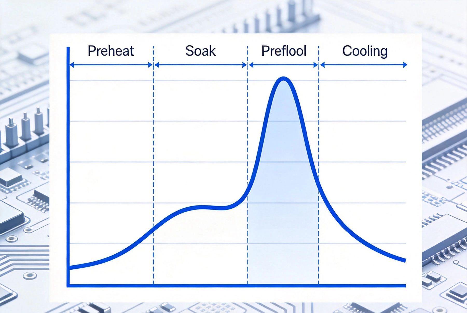
Reflow soldering is a Surface Mount Technology (SMT) assembly process where solder paste— a mixture of solder alloy particles and flux— is deposited onto Pcb pads. Components are then placed onto the paste-coated pads, and the entire assembly passes through a reflow oven where controlled heating melts the solder, forming electrical and mechanical connections.
Why reflow soldering dominates Smt Assembly:
While the concept seems straightforward—apply solder paste, place components, apply heat—the reality involves sophisticated Thermal Management. The temperature profile is the key variable that separates successful assemblies from failures.
A proper reflow temperature profile consists of four distinct stages, each serving specific functions:
The preheat stage gradually raises the assembly temperature from ambient to approximately 150°C (302°F). This gradual heating serves multiple purposes:
Key parameters:
Ramping too quickly causes problems. Rapid heating creates steam pressure from moisture, potentially causing components to pop off the board. It also stresses components and creates thermal gradients across the board.
The soak stage holds the assembly at an elevated temperature, typically 150-200°C (302-392°F), allowing the entire PCB to reach thermal equilibrium. This stage is critical for several reasons:
Key parameters:
The soak duration depends on board complexity, component density, and thermal mass. Large boards with high thermal mass require longer soak times to reach temperature uniformity throughout.
The reflow stage raises temperature above the solder alloy's melting point, causing the solder to melt and form connections. This is the most critical stage for joint formation:
Key parameters:
The peak temperature must be high enough for complete solder melting and proper wetting, but not so high as to damage components or cause excessive intermetallic growth. Lead-free Solder requires higher temperatures than traditional SnPb alloy.
The cooling stage brings the assembly back to ambient temperature, solidifying the solder joints. Controlled cooling prevents thermal damage and affects final joint properties:
Key parameters:
Rapid cooling creates fine-grained solder microstructure with good mechanical properties but increases thermal stress. Slow cooling reduces stress but creates coarser microstructure. The rate must balance these factors.
The temperature profile isn't just a heating schedule—it directly determines Assembly Quality and reliability:
Proper temperature profiles create:- Complete solder wetting on all surfaces- Appropriate fillet shape and volume- No cold solder joints or incomplete connections- Consistent joint appearance across the board
Improper profiles cause:- Cold solder joints from insufficient reflow- Solder balls from volatile splatter- Bridging between adjacent pads- Insufficient solder from inadequate melting
Components experience thermal stress during reflow. Proper profiles minimize this stress by:- Preventing thermal shock from rapid heating/cooling- Keeping component temperatures within specified limits- Minimizing thermal gradients across the board- Avoiding repeated thermal cycles on the same board
Improper thermal treatment causes:- Cracked ceramic capacitors- Delaminated IC packages- Warped plastic components- Damaged temperature-sensitive components
The PCB itself must survive the thermal profile:- FR4 materials have glass transition temperatures (Tg) that shouldn't be exceeded- Thermal expansion mismatches between copper and substrate cause stress- Moisture in the PCB can cause delamination or blistering if heated too quickly- Multilayer boards are particularly sensitive to thermal stress
Proper temperature profiling directly impacts yield:- Reduces rework and scrap rates- Improves first-pass yield- Enables consistent quality across production runs- Reduces hidden defects that cause field failures
No single temperature profile works for all assemblies. Multiple factors influence optimal profile design:
Different solder alloys require different temperature profiles:- Sn63Pb37 (63% tin, 37% lead): Liquidus 183°C, peak 210-230°C- SAC305 (96.5% Sn, 3.0% Ag, 0.5% Cu): Liquidus 217°C, peak 240-260°C- SnAgCu variants: Various liquidus temperatures depending on exact composition- Low-temperature solders: Liquidus as low as 138°C for special applications
Lead-free solders require higher peak temperatures but may have narrower processing windows.
Components have maximum temperature ratings:- Most ICs: 260°C for brief periods- Ceramic capacitors: 260-280°C maximum- Electrolytic capacitors: 105-125°C operating, higher during reflow- Connectors: Plastic components typically rated 200-260°C
Profiles must respect these limits while still achieving proper solder reflow.
PCB material affects thermal behavior:- FR4: Standard material with glass transition at 130-180°C- High-Tg FR4: Tg above 180°C for higher temperature applications- Ceramic substrates: Higher thermal conductivity, different thermal mass- Metal-core PCBs: Superior Thermal Management but require profile adjustment
Larger boards have different thermal characteristics:- Larger thermal mass requires longer soak times- Thermal gradients develop across large boards- Edge effects cause temperature variations- Dense component areas heat slower than open areas
Component arrangement affects local heating:- High-density component areas create thermal mass, slowing local heating- Large thermal planes and ground planes act as heat sinks- Edge-mounted components heat and cool differently- Component height affects air flow and heat transfer
Developing optimal temperature profiles requires systematic approaches:
Begin with solder paste manufacturer specifications:- Recommended ramp rates- Target temperature ranges for each stage- Time above liquidus requirements- Cooling rate guidelines
These provide a starting point tailored to specific solder paste formulations.
Thermal profilers measure actual temperatures during reflow:- Thermocouples attached to test boards- Data logging during production runs- Multiple measurement points to assess uniformity- Real-time temperature monitoring
Profile data reveals actual thermal conditions versus oven settings.
Evaluate profile data against requirements:- Are ramp rates within specifications?- Is soak temperature adequate for flux activation?- Does peak temperature meet solder melting requirements?- Is time above liquidus sufficient?- Are cooling rates controlled?
Identify areas where the profile deviates from targets.
Profile optimization is iterative:- Adjust oven zone temperatures based on data- Modify conveyor speed to change profile duration- Re-measure with thermal profilers- Evaluate solder joint quality visually- Repeat until profile meets all requirements
Even experienced engineers encounter profile issues. Common problems include:
Symptoms: - Cold solder joints- Solder not fully melted- Dull, grainy solder appearance
Causes: - Peak temperature too low- Time above liquidus too short- Ramp to reflow too slow
Solutions: - Increase peak temperature by 5-10°C- Extend time above liquidus- Increase ramp rate to peak
Symptoms: - Cracked components- Delaminated packages- Warped boards
Causes: - Peak temperature exceeds component ratings- Thermal shock from rapid heating/cooling- Excessive time at high temperature
Solutions: - Reduce peak temperature- Decrease ramp rates- Minimize time at peak temperature
Symptoms: - Small solder spheres on the board- Solder splatter on components
Causes: - Rapid preheat ramp causing volatile expansion- Inadequate soak time- Incorrect solder paste application
Solutions: - Reduce preheat ramp rate- Extend soak time- Verify solder paste Stencil Design and application
Symptoms: - Some areas properly reflowed, others not- Uneven solder joint quality
Causes: - Large board with significant thermal mass differences- Improper oven zone settings- Insufficient soak time for thermal equilibrium
Solutions: - Increase soak time- Adjust oven zone temperatures for uniformity- Consider board design changes to reduce thermal mass variations
Symptoms: - Poor solder wetting- Dull solder joints- Solder not flowing properly
Causes: - Soak temperature too low- Soak time too short- Incorrect solder paste
Solutions: - Increase soak temperature- Extend soak duration- Verify solder paste type and age
Contemporary reflow ovens offer advanced profile control capabilities:
Modern ovens feature 7-10 or more heating zones:- Independent temperature control per zone- Precise profile shaping capability- Ability to handle complex thermal requirements- Improved temperature uniformity
Nitrogen environments improve reflow quality:- Reduces oxidation during heating- Improves solder wetting- Extends solder paste pot life- Reduces solder defects
Alternative reflow technology:- Uses vapor condensation for heating- Extremely uniform temperature distribution- Prevents overheating- Suitable for sensitive components
Advanced heating approaches:- Improves temperature uniformity- Reduces thermal gradients- Enables faster profiles- Handles complex boards better
Consistent quality requires ongoing profile monitoring:
Reflow soldering temperature profiles aren't just heating schedules—they're critical process parameters that determine Assembly Quality, reliability, and Manufacturing success. Each stage serves specific functions that must be optimized for your particular solder paste, components, and Pcb Design.
Proper profile optimization requires understanding the four stages, recognizing factors that influence requirements, and systematically measuring and adjusting profiles based on real thermal data. The investment in proper temperature profiling pays dividends in reduced defects, improved yields, and higher product reliability.
Whether you're setting up a new reflow process or optimizing an existing one, temperature profile design deserves careful attention. The difference between successful reflow and solder joint failures often comes down to getting the thermal profile right.
Need help optimizing your reflow temperature profile? Work with solder paste manufacturers and thermal profiling experts who can guide you through profile development. Their experience with similar applications can help you achieve consistent, high-quality solder joints that meet your reliability requirements.
What is PCB Assembly? A Beginner's Guide to the BasicsMay/22/2026
Common PCB Assembly Defects and How to Spot Them VisuallyJuly/30/2026
A Simple Explanation of Wave Soldering for Mixed-Technology BoardsJuly/22/2026
Turnkey vs. Consignment PCB Assembly: Which Model Fits Your Project?August/08/2026
PCB Fabrication and Assembly: What's the Difference?September/30/2026
The Role of Conformal Coating in Protecting Your ElectronicsAugust/14/2026
What is the difference between Surface Mount Technology (SMT) and through-hole assembly?June/04/2026

The Growing Importance of Traceability and Blockchain in PCBAAugust/12/2026