Open Nav


The Ipc-a-610 standard is the most widely referenced inspection standard in the Electronics Assembly industry. Officially titled "Acceptability of Electronic Assemblies," it defines the visual acceptance criteria for Electronic Components mounted on printed circuit boards, covering everything from component placement and solder joints to markings, coatings, and damage criteria. If you work with pcb assembly, you encounter Ipc-a-610 every day, whether you realize it or not. Your manufacturer's quality team uses it. Your customer's procurement engineers reference it. Your defect dispositions are decided against it. Yet many engineers, technicians, and quality managers use it incorrectly, applying it without understanding its structure, its limitations, or the hierarchy of requirements that govern how it should be interpreted.
This guide teaches you how to read the IPC-A-610 standard properly, starting with its organization and class definitions, moving through the critical tables and figures, and finishing with practical guidance on applying it correctly in a Manufacturing or Quality Assurance context.
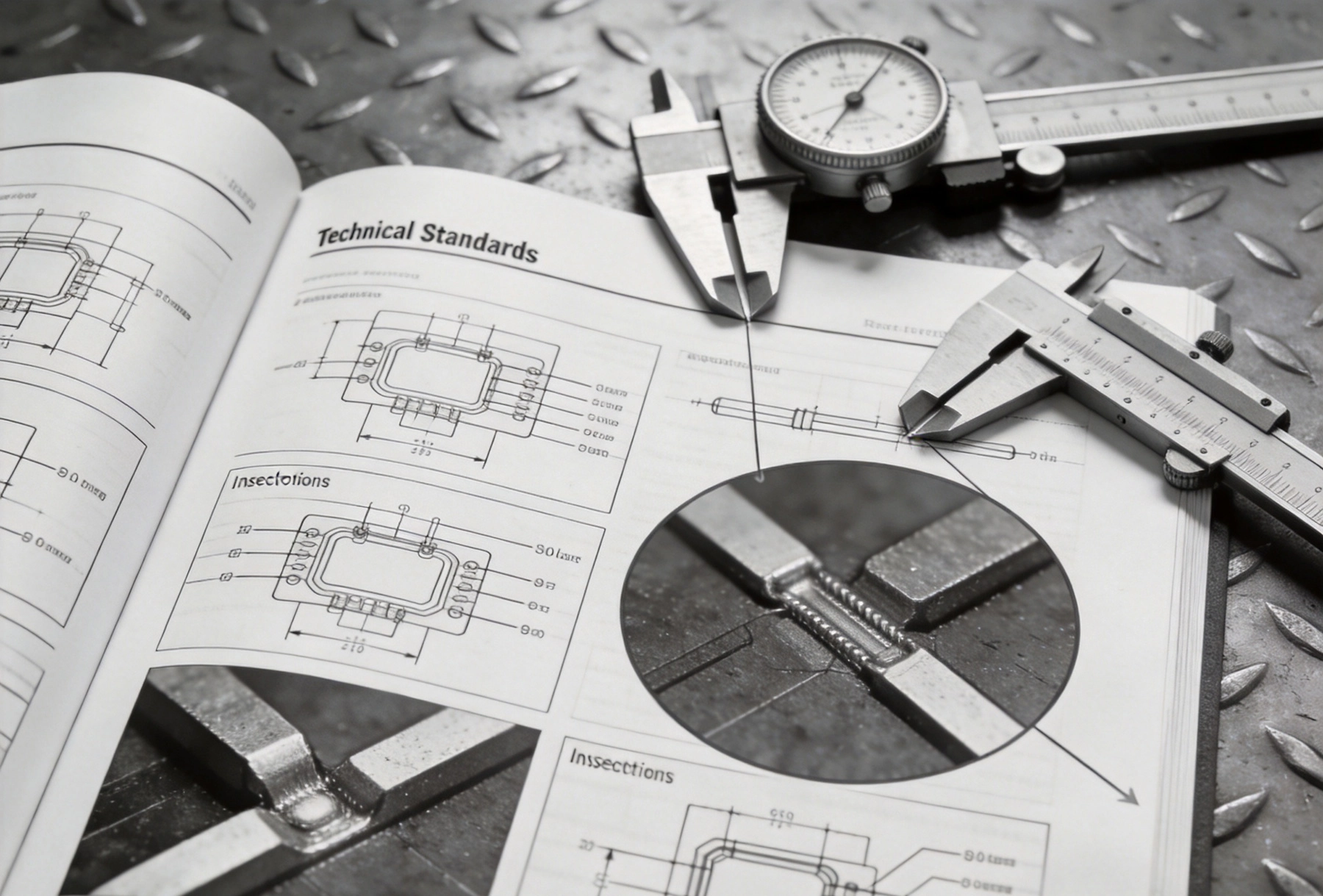
IPC-A-610 is developed and maintained by IPC, formerly the Institute for Printed Circuits, a global trade association that develops standards for the Electronics Manufacturing industry. The standard is revised on a three-year cycle, with the current revision as of recent years being IPC-A-610H. Each revision incorporates updates to address new component technologies, revised industry practices, and feedback from the global user community. Organizations using outdated revisions should plan for periodic updates, as older revisions may not address newer package types or assembly practices.
IPC-A-610 is a Visual Inspection standard. It defines what a properly assembled board looks like and establishes criteria for determining whether observed conditions are acceptable, repairable, or rejectable. It does not prescribe how to achieve those conditions; that is the role of process standards such as IPC-J-STD-001 (soldering requirements) and design standards such as IPC-2221 (Pcb Design). IPC-A-610 assumes that the assembly process meets applicable process standards and evaluates only the visual result of that process.
The standard is used voluntarily by most commercial manufacturers, though many customers specify it contractually, requiring suppliers to demonstrate compliance as a condition of doing business. In aerospace, defense, and automotive industries, IPC-A-610 compliance may be mandated by higher-tier specifications. The standard's authority comes from its broad industry acceptance, not from government regulation, though regulatory bodies often reference it by incorporation.
The most important first step in reading IPC-A-610 correctly is identifying which class of product you are evaluating. The standard defines three classes, each corresponding to a different consequence of failure:
Class 1 covers general electronic products, where the primary requirement is function of the completed assembly. Cosmetic imperfections that do not affect operation are generally acceptable. If a television remote control or a consumer router has a minor solder joint irregularity that does not affect its ability to function, Class 1 criteria typically accept it. The standard gives the assembler and inspector considerable latitude under Class 1.
Class 2 covers dedicated service electronic products, which are expected to have extended service life and high reliability. The consequences of failure are more serious than Class 1, and the criteria are correspondingly tighter. Industrial control equipment, communications infrastructure, and medical devices that are not life-critical fall into Class 2. Inspectors applying Class 2 criteria should expect to reject conditions that would be acceptable under Class 1.
Class 3 covers electronic products where continued performance or expeditious repair is critical. Class 3 applies to aerospace, defense, and life-support equipment where failure is not an option. The criteria are the most stringent in the standard, and the inspector's default position should be rejection unless the specific condition is explicitly covered by an acceptance criterion.
Many assemblies span multiple classes. A medical device that monitors patient vitals is Class 3 for the monitoring circuitry but may be Class 2 for its power supply module if the power supply is independently replaceable and its failure does not directly endanger the patient. The inspector must apply the correct class to each area of the board, not treat the entire assembly as a single class.
IPC-A-610 is organized into seven chapters, followed by a large appendix of illustrated figures. Understanding this structure helps the reader find criteria quickly without reading the entire document.
Chapter 1 covers the scope, purpose, and definitions that apply throughout the standard. This chapter establishes the classification system, defines key terms such as "target," "acceptable," and "defect," and specifies the referenced documents that form the standard's foundation. Every user should read Chapter 1 carefully before applying the standard to any real inspection.
Chapter 2 covers component installation criteria, including component orientation, placement position, lead clinch (for through-hole components), and damage assessment. Component damage is often misunderstood by new users; the standard distinguishes between damage that occurred during Manufacturing and damage that was present on the component when it was received. Only manufacturing damage is subject to IPC-A-610 disposition.
Chapter 3 covers soldering criteria, which is the most extensive section of the standard. This chapter defines acceptance criteria for through-hole solder joints, surface mount solder joints, and tower and the goal is solder connections. Each solder joint type has multiple illustrations showing target, acceptable, and defect conditions. The figures in this chapter are the primary reference for Solder Joint Inspection.
Chapters 4 through 6 cover staking and adhesive, flexible printed boards, and through-hole connections. Chapter 7 covers component installation and hardware. The appendices contain the referenced illustrations, some of which are iconic within the industry: the IPC-A-610F and IPC-A-610H figures showing progressively worse solder joint conditions from target through rejectable have become shorthand for solder joint quality in training programs worldwide.
The body of each chapter contains criteria tables organized by topic, with columns corresponding to each of the three classes. To determine whether a condition meets acceptance criteria, the inspector identifies the relevant section, locates the specific condition being evaluated, and reads across the three class columns to find the acceptance level for the applicable class.
For example, section 3.14 covers circumferential interrupts in plated-through-hole solder fillets. The table specifies maximum allowable lift for each of the three classes. Class 1 allows a certain percentage of the conductor width. Class 2 allows less. Class 3 allows the least. Reading only the Class 1 column when evaluating a Class 3 assembly would result in accepting conditions that are actually rejectable under the correct classification.
The criteria tables use language that can be confusing to new readers. Terms such as "target condition," "acceptable condition," and "defect condition" are defined in Chapter 1 and used consistently throughout. A target condition is the ideal result of a perfect process. An acceptable condition falls within the range of outcomes that the standard permits. A defect condition falls outside that range and requires disposition. The inspector's job is to classify what is observed as acceptable or defective, not to judge whether it meets the target.
Some criteria are stated as maximum or minimum limits. Others reference specific figures. The figures are normative, meaning they are part of the standard and define the acceptance criteria, not merely illustrate them. When a table says "per Figure 3-49," the figure defines the boundary between acceptable and defective, and the inspector must know that figure intimately.
Chapter 3 of IPC-A-610 is where most inspectors spend the majority of their time. It covers solder joint acceptance criteria for every major package type and connection style. Understanding its structure prevents the most common reading errors.
Surface mount solder joint criteria are organized by component type: chip components (rectangular or square end chips), J-leads, Gull-wing leads, butt joints, and column grid arrays. Each type has a distinct solder joint geometry and a distinct set of acceptance criteria that account for how that geometry forms during reflow.
The general requirement for all surface mount solder joints is: sufficient solder, proper wetting, no damage to the component or land, and proper fillet geometry. The standard provides specific criteria for each of these elements. For chip components, the primary criteria are fillet height (how far the solder climbs up the component termination), fillet width (how far the solder extends along the land), and toe wetting (whether solder has flowed around the component's end to wet the top surface of the termination).
For Gull-wing packages such as QFPs and PLCCs, the primary criteria are side fillet formation and heel fillet geometry. The inspector evaluates whether solder has flowed to form a concave fillet on the side of the lead, whether the heel fillet is concave or flat, and whether there is sufficient standoff height. The standard provides minimum acceptable fillet dimensions that vary by component size and lead pitch.
For Bga and column grid array (CGA) packages, the standard provides criteria for solder ball deformation under the package, which is the primary indicator of joint formation. The inspector does not see the actual solder joint between the Bga sphere and the pad, but can infer joint quality from the degree of collapse and the consistency of the resulting shape across all balls. X-ray inspection supplements Visual Inspection for these packages.
The most frequent error in applying IPC-A-610 is treating it as a process specification rather than an acceptance standard. The standard defines the minimum acceptable result, not the recommended process parameters. A board that meets IPC-A-610 criteria may still have been produced through an inferior process that carries higher latent defect risk. Conversely, a board produced through an excellent process may have a cosmetic imperfection that technically violates a criterion but has no impact on reliability. The inspector must understand both what the standard says and what it means for the specific application.
Another common error is applying criteria from the wrong class. This typically occurs when a Class 3 product has a section that is clearly less critical than the rest of the board. The inspector's judgment that a particular section "feels like Class 2" is not a valid basis for applying different criteria. If the board is classified as Class 3, all applicable criteria from Class 3 apply unless a specific section has been formally documented as a lower classification.
A third error is reading criteria tables without consulting the referenced figures. The figures are where the visual standard is actually defined, and the tables are summaries that reference the figures. An inspector who has memorized the tables but not internalized the figures will misinterpret conditions that fall near the boundary between classes.
Finally, some users apply IPC-A-610 to conditions that the standard explicitly excludes. The standard does not cover components that arrived from the supplier already damaged, nor does it cover boards that have been reworked beyond the scope of the applicable rework standard (IPC-A-610R or IPC-7711/7721). Boards that have been reworked must be evaluated against the rework criteria, which are different from the initial assembly criteria.
The three-category system of target, acceptable, and defect conditions is central to IPC-A-610 and is often misunderstood. Understanding this system prevents both over-rejection (rejecting boards that meet the standard) and under-rejection (accepting boards that should be rejected).
Target conditions are aspirational. A target solder joint has ideal geometry, complete wetting, and no visible imperfections. The standard explicitly states that target conditions are not required. Meeting the target is desirable and reflects an excellent process, but it is not the acceptance threshold.
Acceptable conditions fall within a range that the standard defines as fit for purpose. An acceptable solder joint may have minor imperfections that are explicitly permitted by the criteria tables. These imperfections do not affect the joint's reliability under normal service conditions. The inspector should not reject acceptable conditions merely because they do not meet the target.
Defect conditions fall outside the acceptable range and require disposition. In production, defect disposition typically means rework (repairing the defect) or scrap (discarding the board). Under some customer quality agreements, defect conditions may require engineering review and a formal deviation or concession before the board can proceed. The inspector must not accept defect conditions as acceptable based on an assumption that the defect is harmless or unlikely to cause failure.
IPC-A-610 does not exist in isolation. It works in conjunction with a family of related standards that cover the processes that produce the assemblies it inspects.
IPC-J-STD-001 is the soldering process standard, defining the material and process requirements for producing soldered electronic assemblies. Where IPC-A-610 evaluates the result, IPC-J-STD-001 evaluates the process that produces the result. An assembly that passes IPC-A-610 inspection may fail IPC-J-STD-001 if the process used to produce it was non-compliant, even if the visual result met acceptance criteria.
IPC-7711 and IPC-7721 are the rework standards, covering the repair and rework of electronic assemblies. These standards define how to properly repair defects that IPC-A-610 identifies. They also establish criteria for rework work, which differ from initial assembly criteria. A board that has been reworked is evaluated against rework criteria, not against first-pass acceptance criteria.
IPC-A-610 should be read in context with these related standards. An organization that trains inspectors on IPC-A-610 alone, without exposing them to IPC-J-STD-001, will produce inspectors who understand what to reject but not why the conditions they reject are defective. Engineers and quality managers who read the process standard alongside the inspection standard develop a more complete understanding of quality and can make better decisions about disposition of borderline conditions.
IPC-A-610 includes provisions for inspector training and certification. The standard recognizes three certification levels: Certified IPC Specialist (CIS), Certified IPC Trainer (CIT), and Master IPC Trainer (MIT). CIS training is for inspectors and engineers who apply the standard daily. CIT training is for those who will train CIS candidates within their organization. MIT training is for those who will develop and deliver training programs.
Certification requires passing an examination that tests both knowledge of the standard content and the ability to apply it to illustrated example conditions. Many companies require CIS certification as a condition of employment for quality inspectors, and some customers require that a percentage of a supplier's inspection staff hold current IPC-A-610 certification.
Certification is valid for a period of two years, after which recertification is required. The recertification process is typically shorter than the initial certification but covers the current revision of the standard. Inspectors who allow certification to lapse should be retrained before resuming inspection duties, as the standard revisions can introduce new criteria or modify existing ones.
The IPC-A-610 standard is an essential reference for anyone involved in electronic Assembly Quality, but its value is only realized when it is read and applied correctly. Understanding the class system, knowing how to navigate the criteria tables, distinguishing acceptable from target from defect conditions, and recognizing the standard's relationship to process and rework standards all contribute to competent application. Inspectors who invest in deep familiarity with the figures and tables, rather than relying on memorized summaries, develop the judgment needed to handle the borderline cases that summaries cannot cover.
The standard is updated regularly to keep pace with changes in technology and industry practice. Engineers and quality managers should track new revisions, participate in IPC user group meetings where possible, and update their training and documentation to reflect the current revision. Using an outdated version of the standard creates the risk of applying criteria that have been superseded, potentially accepting conditions that are now considered defective or rejecting conditions that are now acceptable under updated criteria.
IPC-A-610 is a visual inspection standard that defines acceptability criteria for completed assemblies. IPC-J-STD-001 is a process standard that defines material and process requirements for producing soldered assemblies. A board can pass IPC-A-610 inspection while being produced through a process that does not meet IPC-J-STD-001 requirements. Both standards are used together in a complete Quality Management system.
The applicable class is determined by the consequence of failure. Class 1 applies to general consumer products where minor failures are tolerable. Class 2 applies to industrial and commercial products with extended service life requirements. Class 3 applies to aerospace, defense, medical life-support, and other critical applications where failure is not acceptable. When in doubt, apply the highest applicable class, as it provides the greatest safety margin.
Yes. Customer specifications that impose stricter requirements than IPC-A-610 take precedence over the standard. If a customer requires Class 3 criteria on a product that would normally be Class 1, the customer's specification governs. Conversely, if a customer explicitly waives specific criteria in writing, those waived criteria do not apply. All deviations from IPC-A-610 requirements should be documented in the quality agreement between buyer and supplier.
When a condition is not explicitly addressed by IPC-A-610, the inspector should consult IPC-A-610 Chapter 1, which provides guidance on undefined conditions. The general principle is that undefined conditions should be evaluated based on the worst-case similar condition that is defined in the standard, erring on the side of rejection when judgment is uncertain. For critical applications, engineering review and customer consultation are appropriate before disposition.
IPC-A-610 is revised approximately every three years. Revisions may add new criteria for new component types, update criteria for existing package styles, modify class definitions, and incorporate feedback from the global user community. Organizations using IPC-A-610 should maintain awareness of revision cycles and plan for periodic training updates when new revisions are released.

Thermal Relief Design: Balancing Heat Dissipation and SolderabilityJuly/23/2026
Panelization Strategies: V-Scoring vs. Tab Routing for Efficient DepanelingJuly/07/2026

How to Reduce PCB Assembly Cost Without Sacrificing QualityOctober/22/2026
Optimizing Pad Design to Prevent Tombstoning and BridgingJune/05/2026

China's Role in the Global PCB Assembly Ecosystem: A 2026 UpdateAugust/11/2026

The Science of Solder Paste Printing: Stencil Design Best PracticesJune/17/2026

Designing for Testability (DFT): Placing Test Points for ICT and FCTJuly/31/2026
Managing Moisture Sensitivity Levels (MSL) for BGA and QFN PackagesAugust/10/2026