Open Nav


Every printed circuit board begins its Manufacturing life as part of a larger panel—a rectangular array of identical boards joined together before being separated into individual units. This panelization strategy, invisible to most Pcb buyers, profoundly affects Manufacturing efficiency, assembly yield, component placement accuracy, and ultimately the cost of every board you purchase. Choose correctly, and your boards flow smoothly through fabrication, assembly, and depaneling with minimal scrap and maximum throughput. Choose poorly, and you face warped panels, cracked components, delaminated boards, and assembly lines that jam at exactly the wrong moment.
The two dominant panelization strategies—V-scoring and tab routing—each excel in different contexts. Understanding when to apply each, and how to implement them correctly, separates well-engineered panel designs from ones that create problems throughout the production lifecycle.
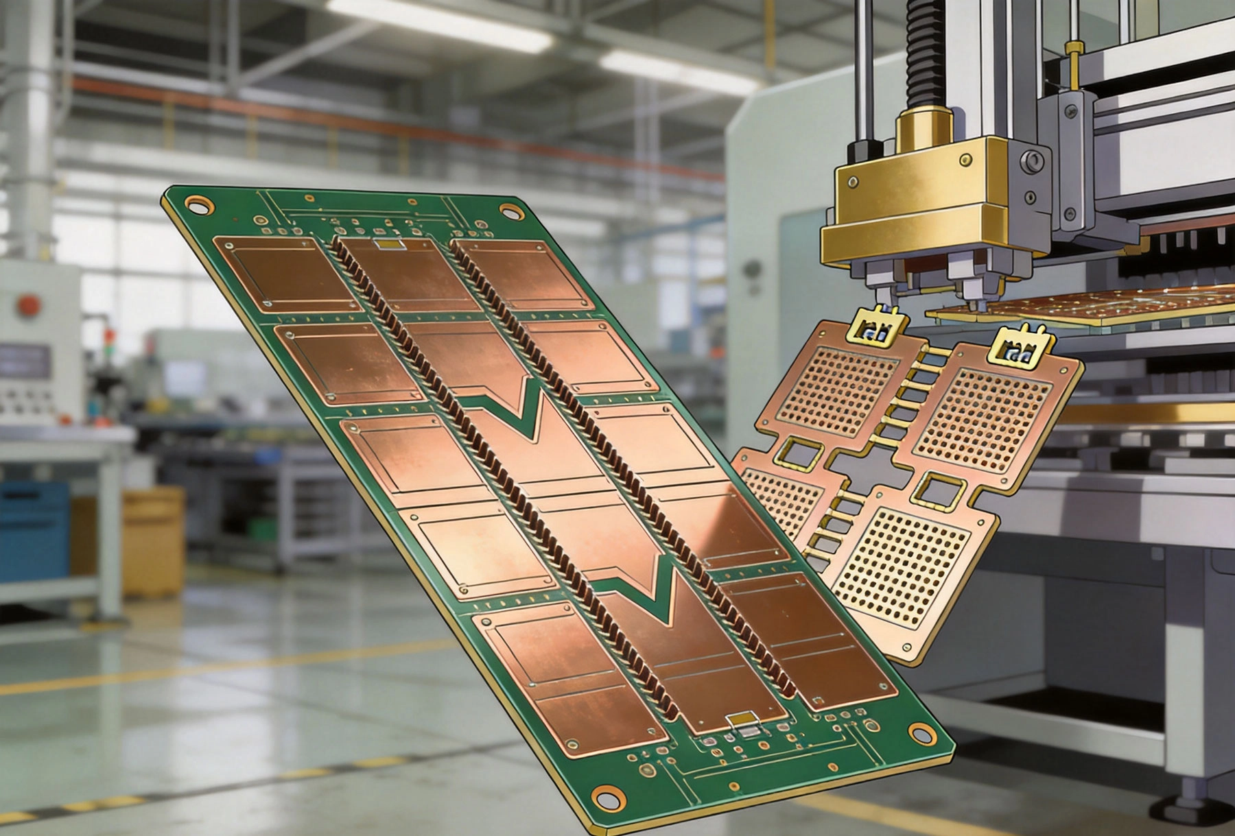
Panelization exists for fundamentally practical reasons. Manufacturing processes—lamination, drilling, plating, imaging, etching, solder mask application—all work more efficiently on larger panels that can be handled by standard equipment. Individual boards, particularly small ones, would be difficult to process and nearly impossible to handle without damage. Panelization enables manufacturers to process many boards simultaneously while maintaining the quality standards that assembled PCBs require.
For the assembly phase, panelization provides additional critical functions. Panels provide structural support during Solder Paste Printing and component placement, preventing flexure that would misalign components or damage fine-pitch leads. The panel acts as a fixture, holding boards in precise positions relative to each other while automated equipment processes the entire array. Without panelization, assembly equipment would struggle to handle individual small boards with the precision that modern Surface Mount Technology demands.
Depaneling—the process of separating individual boards from the panel—represents the transition point where panelization strategy has its most direct impact. How boards are joined, how they will be separated, and what stress the separation process places on components and board material all flow from panelization decisions made during design. Getting this right prevents the most common panelization-related failures that haunt electronics manufacturers.
V-scoring creates narrow V-shaped grooves along the cut lines where individual boards will be separated. The grooves are machined into both sides of the panel, leaving a small amount of material—the score web—connecting all boards within the panel. This web is thin enough to be broken cleanly by applying manual pressure or using a depaneling machine, while thick enough to maintain panel integrity throughout the assembly process.
The V-scoring process uses carbide or diamond-tipped saw blades shaped to create the characteristic V profile. The included angle of the V typically ranges from 30 to 45 degrees, with the specific angle determined by panel thickness and the breaking method used. Deeper scores remove more material, making the break easier but potentially compromising board edge quality. Shallower scores preserve more material at the edge but require more force to break.
Score depth requires careful optimization. The goal is to penetrate approximately one-third of the panel thickness on each side, leaving a central web that holds boards together during assembly but separates cleanly under breaking stress. Too shallow a score risks incomplete separation, with boards that bend excessively before breaking and potentially crack near the score line. Too deep a score weakens the panel too much, risking panel breakage during handling or assembly processing.
V-scoring offers several compelling advantages that explain its widespread adoption in Pcb Manufacturing.
Minimal kerf loss maximizes usable panel area. The V-groove consumes only a narrow strip of panel material—typically 0.8mm to 1.2mm total width. For boards where maximizing panel utilization matters, this efficiency advantage compounds across large production runs. When manufacturing small boards in large quantities, the accumulated area savings from narrow score lanes can significantly improve material economics.
Clean edge quality results from the controlled fracture process. When scores are properly executed and the web breaks cleanly, V-scored boards exhibit smooth edges without the roughness characteristic of routed cuts. For boards with components near the edges, clean edges matter for assembly and potentially for the product's appearance in the final application.
High-speed depaneling with automated equipment makes V-scoring ideal for high-volume production. V-cut depaneling machines apply controlled force along the score line, separating boards rapidly and consistently. These machines can process hundreds of boards per minute with minimal operator intervention, making V-scoring the preferred choice for assembly lines where throughput is paramount.
Lower tooling cost compared to tab routing provides economic advantages for high-volume production. V-scoring requires only the initial blade setup and periodic replacement as blades wear, without the complex programming that tab routing demands. For large production runs where setup costs amortize across many panels, this economic advantage becomes significant.
Despite its advantages, V-scoring carries limitations that restrict its applicability to certain board designs.
Board geometry constraints limit V-scoring to straight-line cuts only. The score blade follows a linear path, making V-scoring unsuitable for panels with curved separation lines, angled cuts, or complex shapes. Attempting to V-score complex geometries either proves impossible with standard equipment or requires expensive custom blade fabrication.
Component clearance requirements demand adequate space from score lines. Components mounted near board edges may not survive the depaneling stress if they're positioned too close to where the fracture propagates. The breaking process creates stress that can crack ceramic capacitors, lift chip components, or damage solder joints near the score line. Minimum clearance recommendations typically specify 3mm to 5mm from any component body to the score line, though exact requirements depend on component type and size.
Panel thickness limitations restrict V-scoring to standard board thicknesses. Very thin boards (below 0.8mm) may not have sufficient web material to survive assembly processing, while very thick boards (above 2.4mm) require excessive force to break cleanly. The optimal thickness range for V-scoring falls between 1.0mm and 2.0mm, covering the majority of standard Pcb applications.
Double-sided assembly complexity increases when boards must be processed on both sides. The V-score groove, while thin, still creates a discontinuity in the panel that may affect processing on the second side. Careful coordination between fabrication and assembly is necessary to ensure that the score doesn't interfere with second-side processing.
Tab routing uses a programmed routing machine to cut around each board's perimeter while leaving small tab bridges—typically 2mm to 5mm wide—at regular intervals. These tabs hold the individual boards within the panel array, maintaining structural integrity during assembly processing while allowing clean separation when depaneling is required.
The routing process uses spindle speeds and feed rates optimized for the panel material, creating clean cuts through the full panel thickness. Modern routing equipment maintains tight positional accuracy, ensuring that cut lines precisely follow the programmed path. The routed slot width—determined by tool diameter—creates the kerf loss, typically 1.5mm to 3.0mm depending on tool size.
Tab placement and sizing require thoughtful design. Too few tabs, or tabs that are too small, risk panel breakage during handling or assembly processing. Too many tabs, or tabs that are too large, make depaneling more difficult and increase the stress on boards during separation. The goal is adequate panel strength throughout assembly while maintaining manageable depaneling forces.
Tab routing's flexibility makes it the appropriate choice for a broader range of panel designs than V-scoring can accommodate.
Geometric freedom represents tab routing's most significant advantage. Any shape that can be programmed into the routing machine can be panelized, including curved outlines, angled cuts, and complex board shapes that V-scoring simply cannot address. For boards with non-rectangular outlines, irregular shapes, or cutouts within the board area, tab routing provides the only practical panelization option.
Reduced stress on edge components makes tab routing safer for assemblies with components near the board perimeter. The controlled routing cut creates minimal stress propagation into the board material away from the cut line. Components can sit closer to the board edge without the risk of depaneling damage that affects V-scored boards.
Better suited for mixed-technology assemblies that include both SMT and through-hole components with tall profiles. The routing process creates clean slots without generating the mechanical stress that breaking a V-score would produce. Assemblies with heavy components, connectors, or battery holders that might shift under breaking stress benefit from the gentler tab routing separation.
Accommodates panel board count flexibility more easily than V-scoring. When panel utilization requirements change or board quantities vary, modifying tab routing programs requires only software changes. V-scoring panel modifications may require physical rework of scoring blades and fixture adjustments.
Tab routing's flexibility comes with tradeoffs that affect manufacturing efficiency and cost.
Greater kerf loss consumes more panel area than V-scoring. The routed slot width must accommodate the tool diameter plus clearance for tool deflection and positional accuracy. For small boards in large quantities, this accumulated area loss affects material utilization and ultimately per-board cost.
Longer processing time compared to V-scoring extends panel cycle time. Each board outline must be individually routed, with the machine following the complete perimeter of every board in the panel. For panels with many small boards, this routing time accumulates significantly. High-volume production of simple rectangular boards may not justify the routing time investment.
Higher tooling cost for specialized routing bits and machine programming adds setup overhead. While standard rectangular panel programs are well-established, unusual geometries or small production quantities may require custom programming that increases initial costs. Tool wear also requires periodic replacement and careful monitoring to maintain cut quality.
Potential for debris generation during routing requires cleanup processing. Fiberglass and epoxy dust created during routing can contaminate the panel surface if not properly managed. Additional cleaning steps may be required before assembly processing can proceed.
The method used to separate boards from the panel should guide panelization strategy from the earliest design stages. Different depaneling approaches impose different requirements on the panelization design.
Manual Breaking
The simplest V-scoring depaneling method applies manual pressure along the score line until the web breaks. This approach suits low-volume production and prototype quantities where equipment investment isn't justified. However, manual technique significantly affects outcome quality—inconsistent force application can create rough edges, propagate cracks beyond the score line, or damage nearby components. For production quantities, manual breaking rarely provides consistent enough quality.
Semi-Automated V-Cut Depaneling
Motorized V-cut machines apply controlled force along the score line, either through a single pressing action or a progressive routing motion. These machines achieve much higher consistency than manual breaking, with programmable force profiles that match specific panel requirements. For moderate production volumes, semi-automated depaneling offers a good balance of equipment cost and process quality.
Fully Automated Depaneling Systems
High-volume production often employs fully automated depaneling systems that integrate with assembly lines. These systems may use V-cut separation, router-based separation, or laser cutting depending on the panelization strategy and throughput requirements. Integration with assembly conveyor systems enables continuous flow processing that maximizes throughput for the highest-volume applications.
Laser Depaneling
For the most demanding applications, particularly those with ultra-fine components near separation lines, laser depaneling offers precision without mechanical stress. The laser vaporizes material along the cut line without physical contact, eliminating the stress propagation that mechanical separation methods create. However, laser depaneling carries significant cost premiums and slower throughput compared to mechanical methods.
The choice between V-scoring and tab routing need not be binary. Many panel designs benefit from hybrid approaches that apply each method where it provides the most value.
A common hybrid pattern uses V-scoring for the majority of separation lines while incorporating tab routing for sections where V-scoring isn't suitable. Boards with deep cutouts, unusual shapes, or components very close to specific edges might receive routed sections while maintaining V-scored straight-line separations elsewhere. This approach optimizes the balance between manufacturing efficiency and design flexibility.
Another hybrid strategy uses tab routing for panel fabrication while incorporating V-scores within individual boards for internal features. Some board designs include scores within the board area—not for depaneling but for user-accessible breakaway tabs or flex sections. These internal scores are typically routed separately from panel separation scores and require different blade configurations and process parameters.
Successful panelization begins at the design stage, with decisions that enable efficient manufacturing rather than creating unnecessary constraints.
Standardize Panel Sizes
Whenever possible, design boards to fit standard panel sizes used by your contract manufacturers. Standardization reduces setup time and material waste, translating to lower manufacturing costs. When your board dimensions are derived from whatever leftover space exists after component layout, you pay for the inefficiency of non-standard panel utilization.
Consider Board Orientation for Depaneling
Position score lines and routing paths relative to component placement to minimize stress on vulnerable components. If boards will be V-scored, orient them so that the most stress-sensitive components sit furthest from predicted fracture lines. Route tab locations away from areas with heavy components or tall packages.
Leave Adequate Panel Margin
Manufacturers require clearance from panel edges for handling and processing. Typically, a minimum of 3mm to 5mm from the outermost boards to the panel edge accommodates standard tooling and fixturing. Boards that extend to panel edges risk damage during handling or may not be processable with standard equipment.
Account for Fiducial Markers
Panel fiducial markers—precise optical reference points used for assembly alignment—require dedicated space outside board areas. Design panelization to include locations for Fiducial Marks that won't be obscured by components, board outlines, or score/routing paths. Standard fiducial locations at panel corners and possibly center positions enable reliable machine vision alignment throughout assembly.
Verify Tooling Test Coupons
Your panel design should include space for tooling test coupons—small test structures used to verify drilling, plating, and other process parameters. Standard coupon designs are available from most manufacturers and should be incorporated into your panelization plan rather than being afterthought additions.
Panelization errors discovered after design completion create costly respins or manufacturing compromises. Several recurring mistakes deserve explicit attention.
Insufficient Component Clearance from Edges
Designing components closer to board edges than the panelization method can safely accommodate creates assembly or depaneling problems. Ceramic chip capacitors, in particular, are prone to cracking when stressed by depaneling forces. Always verify minimum clearances before finalizing board layout.
Score Lines Through Pads or Traces
V-score lines positioned over routing traces, component pads, or vias create reliability problems. The score groove removes material at the board edge, potentially cutting through features that should maintain full thickness. The break line should pass through empty substrate only, not through any conductive features.
Overly Complex Panel Shapes
Intricate panel shapes with many small or oddly-shaped boards may be theoretically producible but practically inefficient. The manufacturing overhead for complex panels—setup time, tool changes, reduced throughput—may make individual board fabrication more cost-effective than panelization at all.
Ignoring Depaneling Method in Design
Designing without considering how boards will actually be separated leads to mismatches between design assumptions and manufacturing capabilities. Confirm the intended depaneling method with your manufacturer early, and design panelization to match that method's requirements.
Panelization choices directly affect manufacturing cost in ways that merit explicit attention during design and procurement.
Material Utilization
The ratio of total board area to total panel area determines raw material efficiency. Higher utilization means less material waste per good board, directly reducing material cost. V-scoring typically achieves 70% to 85% utilization, while tab routing achieves 60% to 75% depending on board complexity and tab count. For high-volume production of small boards, the utilization difference compounds significantly.
Processing Time
Tab routing time scales with the total perimeter of all boards in the panel. A panel containing fifty small boards requires routing fifty separate perimeters, consuming more machine time than a panel with five larger boards having equivalent total area. This processing time directly affects manufacturing cost and lead time.
Depaneling Equipment
Manual depaneling carries lowest equipment cost but highest labor cost and quality variability. Automated depaneling equipment represents significant capital investment but reduces per-board processing cost for high volumes. The optimal balance depends on production quantity, board complexity, and quality requirements.
Rework and Scrap Rates
Poor panelization choices increase scrap rates during depaneling—boards damaged during separation, delaminated by excessive stress, or rejected due to edge quality issues. These scrap costs flow directly into effective per-good-board pricing. Choosing panelization methods appropriate for the board design reduces scrap and improves overall economics.
Different industry segments have developed panelization preferences reflecting their specific requirements.
Consumer Electronics
High volumes and cost sensitivity drive consumer electronics toward V-scoring where designs permit. The throughput advantages and lower per-board cost align with tight margin requirements. Consumer products can often accommodate the component clearance requirements that V-scoring imposes.
Automotive quality requirements often favor tab routing for its gentler depaneling characteristics. The reduced stress on components improves long-term reliability in harsh automotive environments. Some automotive specifications explicitly prohibit V-scoring due to reliability concerns.
Medical Electronics
Medical Device Manufacturing may require specific depaneling methods based on regulatory considerations. Traceability requirements, cleanliness standards, and reliability expectations can influence panelization choice. Close coordination with contract manufacturers on medical programs ensures compliance with applicable requirements.
Aerospace and Defense
Military and aerospace specifications often reference detailed panelization requirements. Ipc Standards and specific program requirements may dictate panelization approach, particularly for high-reliability applications. Verify applicable specifications before finalizing panelization design.
Panelization strategy—choosing between V-scoring, tab routing, and hybrid approaches—directly affects manufacturing efficiency, Assembly Quality, depaneling reliability, and ultimately the cost of every circuit board you produce. The optimal choice depends on board geometry, component placement, production volume, and industry-specific requirements. Getting this decision right requires understanding the tradeoffs between strategies, clear communication with your manufacturing partners, and design practices that accommodate panelization requirements from the beginning rather than treating them as afterthought considerations. Boards that flow smoothly from panel through assembly to depaneling reflect the accumulated benefits of thoughtful panelization decisions made throughout the design process.
Optimizing Pad Design to Prevent Tombstoning and BridgingJune/05/2026
How to Read an IPC-A-610 Standard for Electronic AssembliesSeptember/08/2026
Silk Screen Best Practices: Improving Readability and Assembly EfficiencySeptember/15/2026
Mastering DFM: Essential Design Rules for Flawless PCB AssemblyMay/22/2026

Understanding Prototype SMT Assembly China: A Step-by-Step GuideSeptember/26/2026
What is Turnkey PCB Assembly? A Beginner's GuideSeptember/23/2026

Thermal Relief Design: Balancing Heat Dissipation and SolderabilityJuly/23/2026
Managing Moisture Sensitivity Levels (MSL) for BGA and QFN PackagesAugust/10/2026