

Artificial intelligence computing demands unprecedented power density from silicon. Modern AI accelerators dissipate hundreds of watts from chips smaller than a credit card, creating thermal challenges that conventional cooling approaches cannot adequately address. As AI models grow more complex and computational requirements escalate, the thermal barrier becomes a fundamental constraint on performance. Understanding advanced thermal management solutions is essential for anyone designing AI hardware or specifying computing infrastructure.
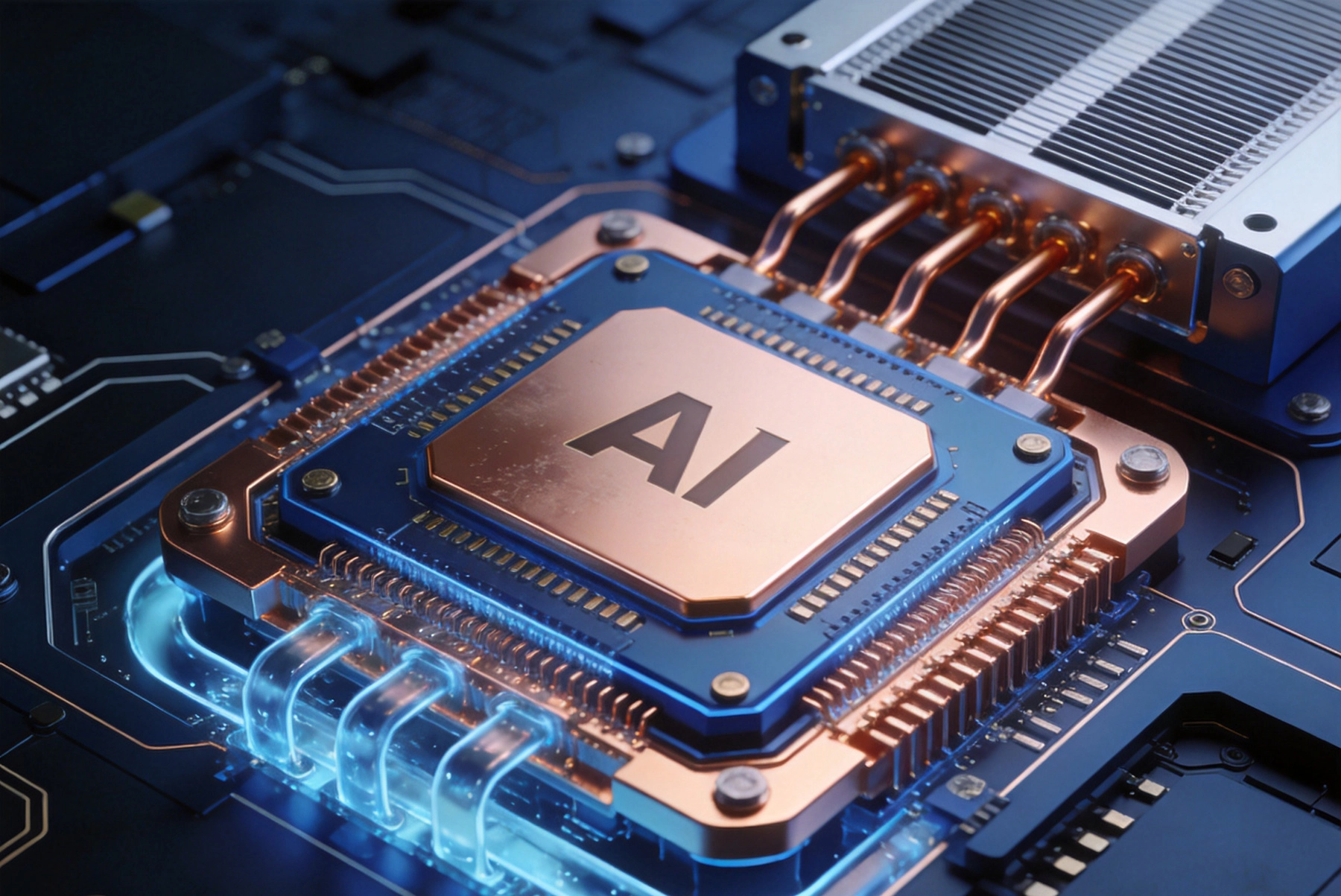
Traditional server processors typically dissipate 100 to 250 watts with thermal design power ratings that have remained relatively stable for years. AI accelerators like NVIDIA H100 and H200 GPUs consume 400 to 700 watts, while newer generations push toward kilowatt-scale power consumption. The computing density required for transformer-based neural networks creates localized hotspots that can exceed 100 watts per square centimeter in critical areas.
Temperature directly affects semiconductor performance and reliability. Every 10 degrees Celsius increase in junction temperature roughly doubles the failure rate of Electronic Components according to the Arrhenius relationship. More immediately relevant, chips must throttle their clock speeds to prevent damage when temperature limits are reached. AI accelerators running thermal benchmarks may deliver only 60-70% of their rated performance when cooling is inadequate.
The distribution of heat generation across an AI chip is highly non-uniform. Compute arrays that execute matrix multiplications produce far more heat than memory controllers or I/O interfaces. This uneven distribution means that peak temperatures in hotspots can exceed the average chip temperature by 30-40 degrees Celsius, requiring thermal solutions that specifically address localized heat concentration.
The substrate that connects an AI chip to its package and board plays a critical role in heat spreading. Advanced organic substrates with embedded copper planes provide thermal conductivity paths from the chip underside to the package base. Multi-layer substrate constructions can include dedicated thermal planes that distribute heat across a larger area before it reaches the cooling solution.
Flip-chip ball grid array (FC-Bga) packaging remains the dominant approach for AI accelerators due to its combination of high I/O density and manageable Manufacturing cost. The flip-chip configuration places the chip active surface facing down, allowing direct thermal contact to the package substrate through thermal interface materials. This geometry enables efficient heat transfer from the die to the package and ultimately to the heatsink.
Some manufacturers use chip-on-wafer-on-substrate (CoWoS) or similar advanced packaging technologies that integrate high-bandwidth memory directly with the compute die. These approaches reduce interconnect power consumption but create additional thermal interfaces that each add resistance to heat flow. Careful management of these layered thermal paths is essential for overall system performance.
Thermal vias transfer heat from the chip through the substrate to reach cooling solutions on the package or board. High-density thermal via arrays beneath the die create low-resistance thermal pathways that spread heat laterally before it reaches the primary cooling interface. Via density, copper fill ratio, and thermal via geometry all affect the overall thermal resistance of this path.
Emerging embedded cooling concepts integrate fluid channels directly into the substrate or package layers. Rather than removing heat at the package surface, these structures allow coolant to flow through the package itself, capturing heat much closer to the source. While still in early adoption phases for commercial AI hardware, embedded cooling represents the direction high-power applications are heading.
Thermal interface materials (TIMs) fill microscopic gaps between surfaces to enable heat transfer. At every interface in the thermal chain, imperfect contact creates air gaps that dramatically reduce thermal conductivity. Even highly polished surfaces have micrometer-scale roughness that traps air and creates resistance to heat flow.
Modern AI packages use multiple TIM layers. Primary TIM sits between the chip die and the integrated heat spreader or vapor chamber. Secondary TIM connects the package to the system-level heatsink. Each layer must be optimized for its specific temperature range, pressure conditions, and required durability. Degradation of TIM over time is a significant reliability concern for systems expected to operate for years.
Material options include thermal greases with high metal oxide content, phase change materials that liquefy at operating temperatures to fill gaps, solderTIMs that metallurgically bond surfaces for ultra-low resistance, and carbon-based thermal interface pads. Each technology has trade-offs between thermal performance, Manufacturing complexity, reliability, and reworkability. AI hardware designers must balance initial thermal performance against long-term field reliability.
Vapor chambers are sealed devices that use phase change to spread heat across large areas. The interior contains a wicking structure saturated with working fluid. When heat is applied at one location, the fluid evaporates, absorbing latent heat. The vapor travels to cooler regions, condenses back to liquid on the wick structure, and capillary action returns the fluid to the heated area.
Vapor chambers effectively eliminate hotspots by spreading heat isotropically across their footprint. A localized 500-watt source on a chip can be spread across a 100-square-centimeter vapor chamber surface before reaching the fins. This dramatically reduces the temperature rise at the source because heat flux per unit area is reduced proportionally.
Integration of vapor chambers into AI accelerator packages has become standard practice for high-power devices. The vapor chamber sits directly beneath the chip or surrounds it, providing an isothermal surface for subsequent heatsink attachment. Some designs integrate micro-jet impingement or micro-channel structures within the vapor chamber to enhance boiling heat transfer at high heat fluxes.
Air-cooled heatsinks for AI accelerators have evolved significantly beyond simple aluminum extrusions. Machined copper heatsinks with micro-fin arrays provide orders of magnitude improvement in surface area compared to older designs. The trend toward thinner fins with higher aspect ratios continues as manufacturing technology improves.
Jet impingement cooling uses high-velocity air or inert gas directed perpendicular to the heatsink surface. This approach disrupts the thermal boundary layer that forms over fins, dramatically improving heat transfer coefficients compared to natural or forced convection. Some AI servers incorporate arrays of micronozzles that create uniform impingement across the entire heatsink footprint.
The tradeoff with aggressive fin geometries is pressure drop and acoustic noise. High-speed fans required to force air through narrow fin channels generate significant noise that may be unacceptable in certain deployment environments. Data center operators increasingly specify acoustic limits that constrain the fan speeds and fin densities that can be used.
Two-phase cooling heatsinks incorporate boiling and condensation cycles to achieve much higher heat transfer coefficients than single-phase air cooling. Working fluid inside the heatsink boils at the chip interface, transporting heat through vapor transport to condensing surfaces elsewhere in the heatsink. The latent heat of vaporization provides orders of magnitude more heat transfer per unit mass flow than sensible heating alone.
These systems typically operate at pressures slightly above atmospheric to prevent the working fluid from boiling at too low a temperature. Some designs use thermoelectric coolers or compressor-based refrigeration to subcool the condensed liquid, improving performance. While more complex than passive air cooling, two-phase heatsinks can dissipate 10-20 times more heat per unit area.
Direct liquid cooling brings coolant into direct contact with the heat source or places it within a single thermal interface distance. Cold plate technology uses channels machined into copper or other high-conductivity materials to flow coolant across the package base. The fluid带走 (carries away) heat directly from the chip package surface.
Cold plate designs for AI accelerators must account for the high heat fluxes involved. Typical cold plate thermal resistance values target 0.1 to 0.2 degrees Celsius per watt, compared to 0.5 to 1.0 C/W for best-in-class air-cooled solutions. Achieving these values requires careful attention to internal flow distribution, surface wetting, and avoidance of vapor locking at high heat fluxes.
Some systems use dielectric coolant that can safely contact electronics directly. These fluorinated liquids have low electrical conductivity and high dielectric strength, allowing them to flow over exposed circuitry without shorting risks. While more expensive than water cooling, direct-to-chip dielectric cooling enables the highest power densities and eliminates the thermal resistance of the package-to-cold-plate interface.
Immersion cooling submerges entire server systems, including AI accelerators, in dielectric liquid. The fluid either boils at component surfaces or remains single-phase depending on the system design. Boiling immersion provides superior heat transfer coefficients but requires careful management of bubble formation and vapor release.
Single-phase immersion systems pump cool fluid through the tank, with components simply convecting heat to the surrounding liquid. This approach is simpler to implement and has become increasingly popular as data centers seek to reduce cooling energy consumption. Operators report cooling energy reductions of 90% or more compared to traditional air cooling with computer room air conditioners.
Infrastructure considerations for immersion cooling include tank design, fluid management, filtration, and serviceability. Components must be designed or selected for compatibility with the immersion fluid, which may swell seals or affect certain coatings over time. Despite these challenges, immersion cooling adoption is accelerating in high-performance computing and AI training clusters.
Water cooling at the rack and row level is becoming standard for AI deployments. Rather than cooling each chip individually, chilled water circulates through manifold systems that serve multiple servers. This approach centralizes cooling infrastructure and reduces the per-server complexity of liquid cooling.
Cooling distribution units manage water temperature, flow rate, and pressure across the rack. Advanced systems use variable-speed pumps and smart controls to optimize cooling based on real-time workload. Waste heat from the water loop can be captured for building heating or rejected through cooling towers or dry coolers.
Water leakage remains the primary concern with rack-level water cooling. Double-walled tubing, leak detection sensors, and automatic shutoff valves provide protection. Some installations route water connections outside the server racks entirely, with quick-disconnect fittings that minimize leak points.
Piezoelectric fans use piezoelectric actuators to oscillate flexible blades at high frequency, creating airflow without moving the motor and bearings of conventional fans. This approach enables thinner fan profiles, lower power consumption, and longer lifetime. Piezoelectric fans are particularly valuable in space-constrained applications where traditional centrifugal fans cannot fit.
Micro-cooler technology integrates micro-scale vapor compression cycles onto chips or packages. These miniature refrigerators use MEMS-fabricated compressors and evaporators to provide localized cooling directly at the heat source. While still primarily in research and development, micro-coolers promise to enable power densities beyond what passive cooling can support.
Thermoelectric coolers use the Peltier effect to actively pump heat from one surface to another when electrical current flows through junction materials. They can reduce chip temperature below ambient conditions, enabling operation in environments where air or water cooling is insufficient.
The efficiency of thermoelectric cooling is limited by the coefficient of performance, which decreases as temperature differential increases. At temperature differences greater than 40-50 degrees Celsius, thermoelectric coolers consume more electrical power than they save by enabling higher chip performance. They work best in applications with modest temperature lift requirements.
AI accelerators are typically installed in servers with multiple GPUs or accelerators sharing airflow. The thermal interaction between components creates challenges for system designers. Upstream components heat air that reaches downstream components, reducing the temperature margin available to devices at the air exit side of the system.
Effective airflow management uses baffles, seals, and directed flow paths to ensure each component receives adequate cool air. Cold aisle containment in data centers isolates the intake air supply from hot exhaust, maximizing the temperature difference available for heat transfer. Computational fluid dynamics simulation helps designers optimize airflow distribution before physical prototypes are built.
Some AI deployments use phase change materials (PCMs) to buffer thermal loads during peak compute periods. PCM embedded in heatsinks absorbs heat as the material melts, temporarily reducing the cooling demand on active systems. This thermal capacitance allows components to run at higher power for short durations before thermal limits are reached.
Power capping and throttling strategies manage the relationship between cooling capacity and compute performance. Rather than designing cooling for absolute maximum power, systems can track thermal headroom and dynamically adjust power allocation across accelerators based on real-time temperature measurements. This approach enables higher average utilization while protecting against thermal excursions.
Chiplet-based designs that integrate multiple smaller dies on an interposer offer advantages for thermal management. Breaking a large monolithic chip into smaller chiplets spreads power dissipation across a larger area, reducing peak heat flux. Each chiplet can be placed optimally for its thermal characteristics.
The interposer substrate in chiplet systems creates new thermal pathways and interfaces. Heat generated in compute chiplets must flow through the interposer and potentially through adjacent chiplets before reaching cooling solutions. Careful thermal simulation helps designers optimize chiplet placement for both electrical performance and thermal distribution.
Wide-bandgap semiconductor materials like gallium nitride and silicon carbide operate at higher temperatures than silicon, reducing cooling requirements for equivalent power levels. These materials also offer superior power efficiency, which translates directly to lower heat generation for the same computational work.
GaN and SiC are primarily used in power delivery and RF applications today, but their adoption in AI accelerator compute elements is being researched. The thermal advantages are compelling, but manufacturing yields and cost at scale remain challenges. As processes mature, wide-bandgap materials may enable the next generation of more power-dense AI hardware.
Optical interconnects eliminate the significant power consumption of electrical signaling between chips and across distances. Lasers and modulators replace copper traces, dramatically reducing heat generation in the interconnects themselves. For AI systems with multiple accelerators, photonic links can substantially reduce total system power consumption.
The thermal challenge with photonics is the efficiency of lasers and the heat generated by modulators and receivers. Heterogeneous integration of photonic elements with silicon compute chips using advanced packaging may enable co-packaged optics that manage thermal interfaces more effectively than discrete solutions.
Begin thermal analysis early in the design cycle when layout options are still flexible. Chip-level thermal simulation identifies hotspots and informs floor planning decisions that can dramatically affect final thermal performance. Moving a hot functional block a few millimeters can change its thermal coupling to cooling solutions significantly.
Model the complete thermal path from junction to ambient. Each interface and component in the heat flow chain contributes resistance. Optimize where the biggest thermal gains are available rather than focusing only on easily changed elements. Often the interface materials and cold plate design offer more improvement potential than changing the chip itself.
Plan for margin in thermal specifications. Components age and TIM degrades over time, increasing thermal resistance. Ambient temperatures in data centers vary seasonally and with workload distribution. Designing for worst-case conditions ensures reliable operation throughout the system lifetime.
AI accelerators demand thermal solutions far beyond conventional air cooling. Power densities exceeding 500 watts per chip require sophisticated combinations of vapor chambers, liquid cooling, and advanced interface materials working together.
Liquid cooling, whether direct-to-chip or immersion, represents the mainstream direction for high-power AI hardware. Water cooling at the rack level and direct liquid cooling at the component level together can remove kilowatts of heat from a single rack while consuming a fraction of the energy required for equivalent air cooling.
Packaging technology continues to evolve, with chiplet architectures and advanced substrates enabling better thermal spreading. Material innovations in thermal interface materials and phase change coolants push the boundaries of what can be cooled passively or with modest active systems.
System-level thermal design integrates these component-level solutions into coherent cooling architectures. Airflow management, power capping strategies, and computational fluid dynamics simulation help designers optimize whole-system thermal performance.
As AI computational demands continue growing faster than cooling technology advances, thermal management becomes the primary constraint on hardware performance. Understanding these thermal solutions positions engineers to make informed decisions about AI hardware design and deployment.
Miniaturization Mastery: Handling 01005 Components and Micro BGAsJune/15/2026
The Evolution of Digital Twins in PCB Assembly Process ControlJuly/13/2026

Flexible and Rigid-Flex PCBs: Meeting the Demand for WearablesJuly/21/2026
Green Manufacturing: Reducing Carbon Footprint in PCB Assembly PlantsSeptember/14/2026
Embedded Component Technology: The Future of Ultra-Compact BoardsJuly/29/2026

The Growing Importance of Traceability and Blockchain in PCBAAugust/12/2026

Top 5 PCB Assembly Trends Shaping the Industry in 2026May/22/2026
Handling 01005 Components and Micro BGAsJune/03/2026