
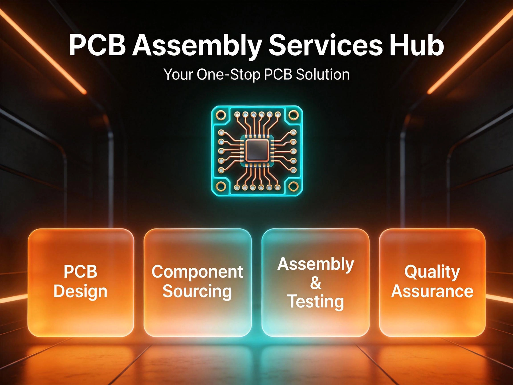
The world of Pcb Assembly has a jargon problem. Walk into a conversation between an electronics engineer and an EMS provider and you'll hear terms like HDI stack-up, ALIVH, Tombstoning, Fiducial Marks, and reflow profile—and that's before anyone mentions BGA inspection or ICT coverage. For newcomers, it can feel like entering a club where everyone knows the secret handshake and you're standing outside holding a sign. This hub exists to change that. Whether you're a hardware startup founder who just closed a seed round, an engineer at an established company spinning up a new product, or a student learning how electronics actually get made, this is your starting point.
We've organized everything around how you actually need it—not how the industry organizes itself internally, but how you think about it when you're trying to get a product built. If you're reading this, you're probably somewhere on the journey from "we have an idea" to "we're shipping units." This hub will help you understand what services are available, how they fit together, and what questions to ask at every stage.
Design for Manufacturability analysis before production
ICT, flying probe, and custom functional test development
Before a single component can be placed, someone has to make the bare board—the green (or white, or black, or red) substrate that holds everything together. Pcb fabrication is the process of taking your design files and transforming them into the physical board: copper traces etched to your specification, dielectric layers laminated, holes drilled, plating applied, solder mask coating applied, and silkscreen markings printed.
Fabrication capabilities vary significantly between manufacturers. Here's what separates the capable from the limited:
| Capability | Standard Shops | Advanced Facilities |
|---|---|---|
| Layer count | 2–12 layers | Up to 40+ layers |
| Minimum trace/space | 0.1mm / 0.1mm | 0.075mm / 0.075mm or tighter |
| Minimum via hole | 0.3mm | 0.15mm–0.2mm |
| Board thickness | 0.4mm–3.2mm standard | 0.2mm–6.0mm+ |
| HDI capability | Limited or none | Full HDI with laser micro-vias |
| RF materials | Standard FR-4 only | Rogers, Taconic, mixed laminates |
Choosing a fabricator is one of the most consequential decisions in your supply chain. Boards that come back with delamination, trace width violations, or plating voids don't just delay your project—they can create field reliability failures that cost far more than the board itself. We invest in the equipment, process control, and testing that eliminates these failure modes before they reach your assembly line.
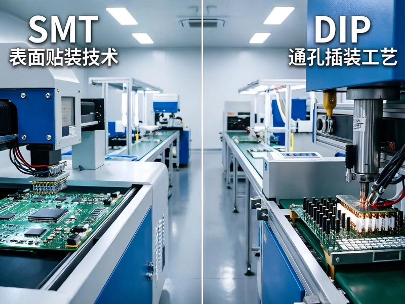
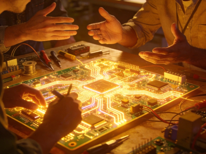
Surface Mount Technology—SMT—is how the vast majority of electronics are assembled today. Components are placed directly onto the surface of the board, without holes, using Solder Paste to hold them in place during reflow. It's faster, cheaper per unit, enables much higher component density, and allows components on both sides of the board. If your product is less than a decade old and fits in your hand, it's almost certainly SMT-assembled.
The SMT process in brief: a steel stencil applies Solder Paste to the board's pads, automated pick-and-place machines position components with micron-level accuracy, and a reflow oven melts the paste into permanent joints through a carefully controlled Temperature Profile. The result: hundreds or thousands of components assembled per board, per minute, with consistent quality.
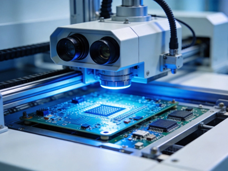
What makes one SMT operation better than another isn't just equipment—it's the combination of machine capability, process discipline, and quality systems that determine first-pass yield and defect escape rates. We run AI-assisted AOI inspection on every board, X-ray verification for hidden joints (BGAs, QFNs), and full electrical test to verify correct assembly before boards ship.
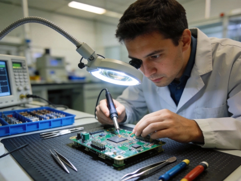
Through-hole technology—THT—was the original Pcb Assembly method and remains essential for applications where mechanical strength, durability, or current-carrying capacity trumps miniaturization. In Through-hole Assembly, component leads are inserted through holes drilled in the board and soldered on the opposite side, creating joints that are mechanically stronger than surface mount equivalents.
Through-hole is the right choice for: connectors that get plugged and unplugged repeatedly, components subject to physical stress or vibration (automotive under-hood, industrial equipment), high-current-carrying parts like power inductors and bus bars, and any application where field serviceability matters. The mechanical robustness of a through-hole joint simply can't be matched by surface mount for these use cases.
Most modern products use a hybrid approach—SMT for the vast majority of components, through-hole for the parts that need it. This hybrid assembly introduces additional process complexity: the board goes through SMT reflow first, then through-hole parts are inserted and soldered separately, typically by Wave Soldering or hand soldering for odd-shaped parts. We have the equipment and expertise to manage mixed-technology assemblies reliably at scale.
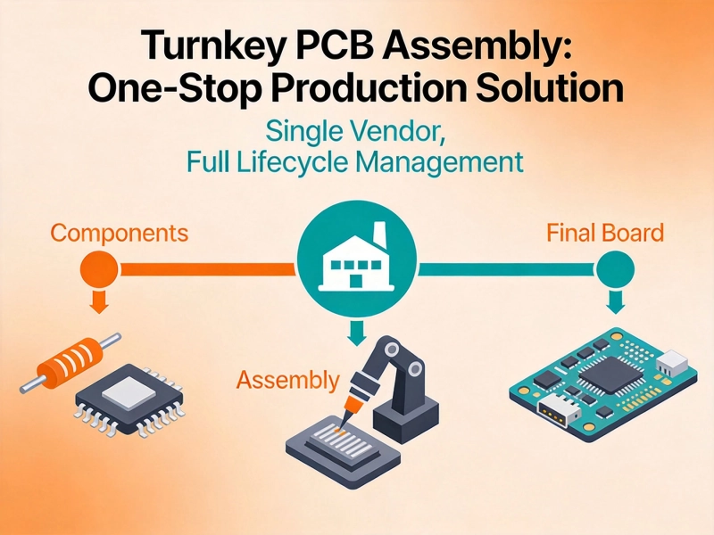
Turnkey Assembly is our most comprehensive service: we take complete ownership of your project from Component Sourcing through finished, tested board delivery. You provide the design files. We deliver the finished product. You deal with one vendor, one invoice, one support contact who knows your project inside and out.
The alternative—consigned or partial assembly, where you source components yourself and ship them to an assembler—is a model that works for some scenarios (prototypes using existing component stock, for instance), but introduces coordination overhead, fragmentation of accountability, and delays that most product teams underestimate. We've written a detailed guide to turnkey vs. partial assembly that covers the economics in detail—but the short version is that turnkey typically delivers faster lead times, better unit economics, and stronger quality accountability for the majority of product builds.
Our turnkey service includes: full BOM review and component sourcing, DFM analysis before production, bare board fabrication, complete SMT and/or through-hole assembly, AOI and X-ray inspection, in-circuit and functional test as required, firmware loading and programming, and complete documentation package including lot traceability.
Here's a number worth remembering: approximately 40–60% of all PCB assembly defects originate from design decisions—not machine errors, not component failures, not operator mistakes, but choices made at the schematic and layout stage that created Manufacturing problems no process could fully compensate for.
Design for Manufacturability review exists to catch those problems before boards are built. Our engineering team reviews your design files against our actual manufacturing capabilities—component spacing, pad geometry, trace routing, via strategy, panelization, test point coverage—and provides specific, actionable feedback on what to change before production begins.
A proper DFM review from a qualified manufacturer catches issues that generic guidelines miss: the specific combination of components on your board, the particular stack-up you've chosen, the real-world tolerances of our equipment. That's information you can only get from a manufacturer who actually knows what their equipment can and can't do—and who has reviewed thousands of designs across dozens of application categories.
Before your first production build. Always. Even if you've built the design before with a different assembler, run it through DFM with your current manufacturer—different equipment, different tolerances, different processes means different manufacturability considerations.
A board that looks visually perfect can still be electrically wrong. Components placed in the wrong orientation, opens in solder joints too subtle for AOI to catch, traces that were damaged during handling—these failures only show up in electrical test. We build testing into every production run as a standard service, not an add-on.
Our testing capabilities include:
Here's what working with us looks like in practice—step by step:
"What I appreciate most about working with this team is that they engage with our design as engineering partners, not just order-takers. The DFM feedback we get before production has saved us from multiple expensive mistakes. And when something does go wrong—and something always goes wrong at some point—they own it completely and fix it fast. That accountability is worth more than any price difference."
— Co-Founder, Hardware Startup, Consumer IoT, San Francisco
It depends on the service. For prototype and NPI builds, we accept orders as small as 5 to 10 boards. For production runs, our minimum is 20 units. These aren't arbitrary numbers—they reflect the fixed setup costs of running a production job regardless of quantity. We do offer volume pricing that makes larger orders increasingly economical, and many customers find that the per-unit cost reduction at 100–500 units makes increasing order quantities attractive.
For standard multilayer boards with components in stock: 10 to 15 business days from quote confirmation to ship date. Complex boards—high layer counts, advanced packages, impedance-controlled RF designs—typically run 15 to 25 business days. The longest variable is always Component Procurement for long-lead items; we work proactively to identify these upfront and discuss options (stock substitutions, pre-ordering, etc.) before they affect your schedule.
Yes, for consigned builds we accept customer-supplied components. The tradeoff is that you own the component quality and availability risk—we can't guarantee turnaround times or defect rates for parts we didn't source. For most product builds, turnkey service where we source components delivers better economics, shorter lead times, and stronger accountability. But if you have specific reasons to supply components—existing stock, qualified parts for regulated industries, particular pricing arrangements—we're happy to work with your parts.
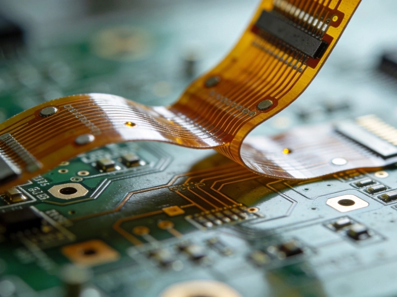
Yes. Rigid-flex and flexible printed circuits require specialized manufacturing processes and design rules different from standard rigid boards. We've built dedicated capability for flex and rigid-flex assembly, including specialized handling, stiffener attachment, and coverlay processes. If you're designing flex or rigid-flex, we recommend engaging with us early in the design phase—before layout is finalized—to ensure the design is optimized for our specific manufacturing processes.
Standard Gerber format (RS-274X or extended Gerber) for board files, Excellon drill files, and IPC-2581 where available. For BOM, we accept Excel, CSV, and PDF formats—Excel or CSV are preferred for automated processing. Pick-and-place files in CSV, Excel, or IPC-7351 format. The more complete your file submission, the more accurate our quote and DFM review will be.
We maintain ISO 9001 Quality Management certification and IATF 16949 for automotive applications. For medical device work, we operate under Iso 13485-aligned quality systems. Our facility undergoes regular third-party audit for all certifications, and we're happy to provide documentation, audit rights, and certificates of conformance as required by your quality system.
If you've read this far, you're probably trying to figure out whether we can handle your project—and you're looking for enough information to make a decision. The honest answer is that the answer depends on your specific requirements. The best next step is to share your design files and requirements with us for a specific review and quote.
That's not a deflection—it's the reality of a service business where every project has unique technical requirements, volume targets, and quality requirements. What we can tell you is this: we invest in the equipment, process control, and engineering expertise to handle a very wide range of PCBA complexity, and we're transparent about the limits of what we can and can't do well. If your project is outside our core capabilities, we'll tell you—and point you to a provider who can help.
If it's within our range, you'll get a detailed quote, honest DFM feedback, and a manufacturing partner who takes accountability for the whole build. That's what our service hub exists to deliver.
Upload your design files, tell us about your project, and receive a detailed quote with DFM feedback within one business day. Whether you're building your first prototype or scaling a product to volume, our team is ready to be your manufacturing partner. No vague pricing, no black-box process—just honest capability assessment and complete accountability for the boards we build.
How We Handle Rush Orders and Quick-Turn PCB PrototypingJuly/08/2026
Our Quality Assurance Promise: AOI, X-Ray, and Functional TestingJune/26/2026
Comprehensive Guide to Our SMT and DIP CapabilitiesJune/09/2026
Customer Success Stories: Real Projects Delivered by Our TeamJuly/17/2026

The Rise of AI Servers and Their Impact on HDI PCB AssemblyJuly/10/2026
Why Choose Turnkey PCB Assembly for Your Next Product Launch?May/22/2026
Addressing Warpage Issues in Thin and Flexible Circuit BoardsJune/29/2026

How Turnkey Providers Streamline Component Procurement and LogisticsJune/18/2026